RFID-Radio Frequency Identification
Discover how Metro Smart Cards work

RFID (RADIO FREQUENCY INDENTIFICATION)
Radio Frequency Identification (RFID) refers to a wireless system comprised of two components: tags and readers. The reader is a device that has one or more antennas that emit radio waves and receive signals back from the RFID tag. Tags, which use radio waves to communicate their identity and other information to nearby readers, can be passive or active. Passive RFID tags are powered by the reader and do not have a battery. Active RFID tags are powered by batteries.
RFID tags can store a range of information from one serial number to several pages of data. Readers can be mobile so that they can be carried by hand, or they can be mounted on a post or overhead. Reader systems can also be built into the architecture of a cabinet, room, or building.
Three families
- Low Frequency (LF) 125/134 kHz
- High Frequency (HF) 13.56 MHz
- Ultra-High Frequency (UHF) 3 GHz
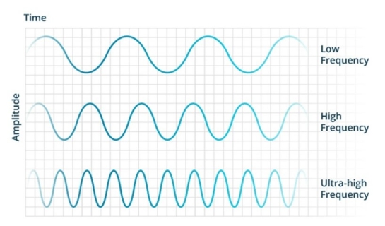
Low Frequency (LF) RFID
Typically, LF RFID systems operate at 125 kHz, although there are some that operate at 134 kHz. This frequency band provides a short read range of 10 cm, and has slower read speed than the higher frequencies, but is not very sensitive to radio wave interference.
High Frequency (HF) RFID
The HF band ranges from 3 to 30 MHz Most HF RFID systems operate at 13.56 MHz with read ranges between 10 cm and 1 m. HF systems experience moderate sensitivity to interference.
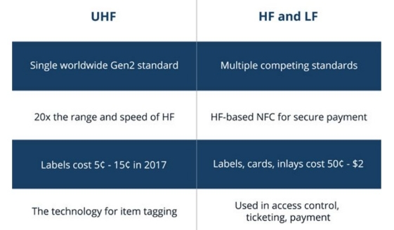
HF RFID is commonly used for ticketing, payment, and data transfer applications
Several HF RFID standards in place, such as the ISO 15693 standard for tracking items, and the ECMA-340 and ISO/IEC 18092 standards for Near Field Communication (NFC), a short-range technology that is commonly used for data exchange between devices. Other HF standards include the ISO/IEC 14443 A and ISO/IEC 14443 standards for MIFARE technology, which used in smart cards and proximity cards, and the JIS X 6319-4 for Felicia, which is a smart card system commonly used in electronic money cards.
Ultra-High Frequency (UHF) RFID
The UHF frequency band covers the range from 300 MHz to 3 GHz. RAIN RFID systems comply with the UHF Gen2 standard and use the 860 to 960 MHz band. While there is some variance in frequency from region to region, RAIN RFID systems in most countries operate between 900 and 915 MHz
The read range of passive UHF systems can be as long as 12 m, and UHF RFID has a faster data transfer rate than LF or HF. UHF RFID is the most sensitive to interference, but many UHF product manufacturers have found ways of designing tags, antennas, and readers to keep performance high even in difficult environments. Passive UHF tags are easier and cheaper to manufacture than LF and HF tags.
Active RFID Systems
In active RFID systems, tags have their own transmitter and power source. Usually, the power source is a battery. Active tags broadcast their own signal to transmit the information stored on their microchips.
Active RFID systems typically operate in the ultra-high frequency (UHF) band and offer a range of up to 100 m. In general, active tags are used on large objects, such as rail cars, big reusable containers, and other assets that need to be tracked over long distances.
There are two main types of active tags: transponders and beacons. Transponders are “woken up” when they receive a radio signal from a reader, and then power on and respond by transmitting a signal back. Because transponders do not actively radiate radio waves until they receive a reader signal, they conserve battery life.
Beacons are often used in real-time locating systems (RTLS), in order to track the precise location of an asset continuously. Unlike transponders, beacons are not powered on by the reader’s signal. Instead, they emit signals at pre-set intervals. Depending on the level of locating accuracy required, beacons can be set to emit signals every few seconds, or once a day. Each beacon’s signal is received by reader antennas that are positioned around the perimeter of the area being monitored, and communicates the tag’s ID information and position.
The wireless ecosystem for customers is very large and growing daily, there are use cases where Active RFID and Passive RFID are deployed simultaneously for an additive approach to asset or sensor management.
Passive RFID System
In passive RFID systems the reader and reader antenna send a radio signal to the tag. The RFID tag then uses the transmitted signal to power on, and reflect energy back to the reader.
Passive RFID systems can operate in the low frequency (LF), high frequency (HF) or ultra-high frequency (UHF) radio bands. As passive system ranges are limited by the power of the tag’s backscatter (the radio signal reflected from the tag back to the reader), they are typically less than 10 m. Because passive tags do not require a power source or transmitter, and only require a tag chip and antenna, they are cheaper, smaller, and easier to manufacture than active tags.
Passive tags can be packaged in many different ways, depending on the specific RFID application requirements. For instance, they may be mounted on a substrate, or sandwiched between an adhesive layer and a paper label to create smart RFID labels. Passive tags may also be embedded in a variety of devices or packages to make the tag resistant to extreme temperatures or harsh chemicals.
CASE STUDY OF THE RFID SYSTEM OF METRO
During my detailed case study on the Coin Token and RFID System, I found the coin/token which we purchase at the ticket counter has a identification number stored in it. Most importantly the amount we will pay will be linked to that number in the centralized server of the system. Now when we use that at the entrance gate, the RFID system recognizes the identification number stored in the token, and the amount linked to this number in the centralized server within half a second.
Now if there’s no money linked to the token/doesn’t recognize, the doors do not open.
If the system recognizes that there’s amount linked to the token, the doors open instantly and notes the entry of token (along with token UID and station name) in the server.
After the completion of journey when we flash the token at the exit gates, the RFID again identifies the ID linked to the token and calculates the journey cost according to the entrance and exit made. (This data is erased from the server in a specified time if it’s a single journey token, hence the metro’s have a “Time Based Token” or “Token Expiry Time” or “Max Time one can stay in a metro environment”, in case of Kolkata Metro, a valid ticket holder can exit from same station within 20 minutes and from other stations within 120 minutes)
If the journey fee is lesser than the amount linked to the token ID, gates open. If not, the gates do not open and you have to pay the remaining fees and exit.
But for cards which are used for multiple journeys, the information with respect to token ID and amount is stored for longer periods. Hence we are able to use the card and when viewing the balance we can see the previous journey details along with the amount paid.
Smart Card
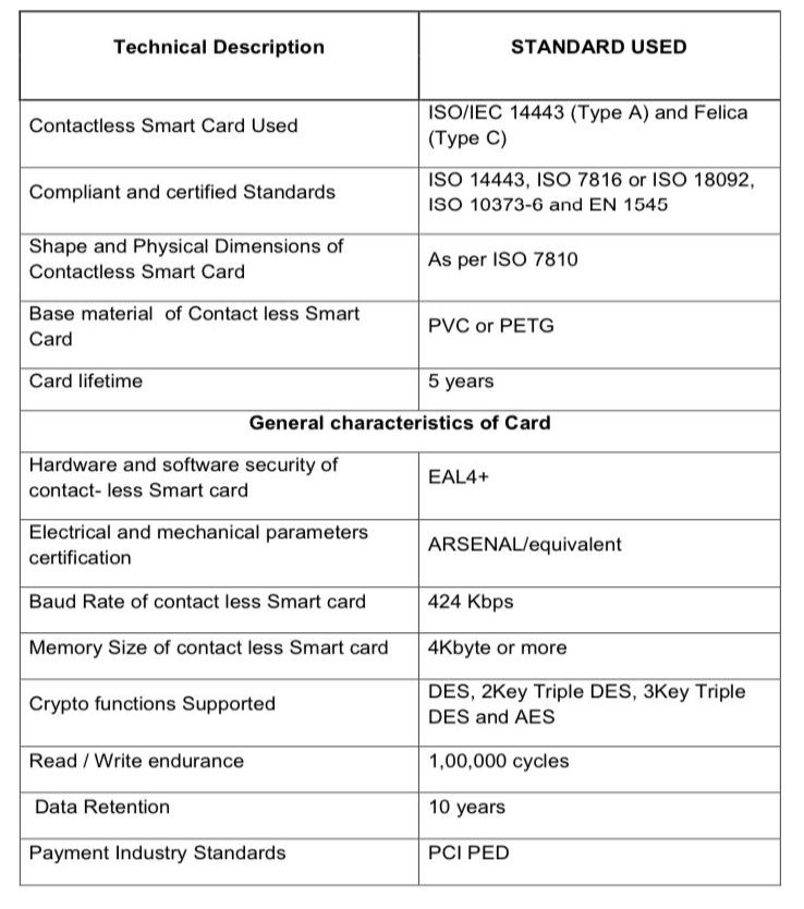
NXP Semiconductors has developed the MIFARE Classic EV1 contactless IC MF2S50yyX/V1 to be used in a contactless smart card according to ISO/IEC 14443 Type A.
A smart card has the following-
- A 9 digit card number
- A LF chip containing 4 bits of storage
- Data transfer of 106 kbit/s
- Typical ticketing transaction time of < 100 ms
- Random ID support
A smart card always starts with a value “01” which determines it’s a card.
Let a card have a UID- “23498753”
In this proposed theory, we determine that the UID remains same unlike PROTOTYPE-1 where the UID is read/write with every travel. The UID is read by the RFID reader and simply authenticates if the UID is present in the server or not, then it proceeds to allocated a value to it (Flag value) in the central server under the UID and the user enters the metro environment. After travelling when the user exits the gate, they subtract the travel fees depending on the stations the user has travelled by using the first value (All the calculations are done in the server therefore keeping the latency low as possible and also keep the entry and exit experience smooth)
This type system is pretty hard to bypass but with few flaw’s it can be hacked/bypassed. Two way’s are-
- If we clone the cards of daily user base, then we can use their UID for our travel without having to recharge the cards.
- If we clone the Master Card i.e. the Station master’s card which allows unlimited travel.
Cards can be cloned using cheap/expensive cloner device, another device is Flipper which captures the radio frequency and data and allows us to replay it to enter and exit.
NOTE: This is a prototype just for illustration, real working would vary.
ABOUT
BLOCK DIAGRAM
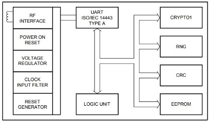
BLOCK DESCRIPTION
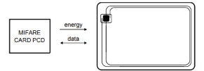
The MF1S50yyX/V1 chip consists of a 1 kB EEPROM, RF interface and Digital Control Unit. Energy and data are transferred via an antenna consisting of a coil with a small number of turns which is directly connected to the MF1S50yyX/V1. No further components are necessary.
- RF interface
- Modulator/demodulator
- Rectifier
- Clock regenerator
- Power-On Reset(POR)
- Voltage regulator
- Anticollision
- Authentication
- Control and Arithmetic Logic Unit
- Crypto Unit
- EEPROM
MEMORY ORGANIZATION
The 1024 x 8 bit EEPROM memory is organized in 16 sectors of 4 blocks. One block contains 16 bytes.
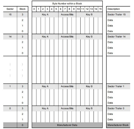
MANUFACTURER BLOCK
This is the first data block (block 0) of the first sector (sector 0). It contains the IC manufacturer data. This block is programmed and write protected in the production test.
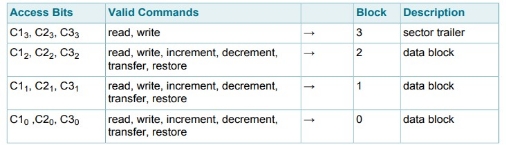
DATA BLOCKS
All sectors contain 3 blocks of 16 bytes for storing data (Sector 0 contains only two data blocks and the read-only manufacturer block). The data blocks can be configured by the access bits as • read/write blocks • value blocks Value blocks can be used for e.g. electronic purse applications, where additional commands like increment and decrement for direct control of the stored value are provided A successful authentication has to be performed to allow any memory operation.
Remark: The default content of the data blocks at delivery is not defined.
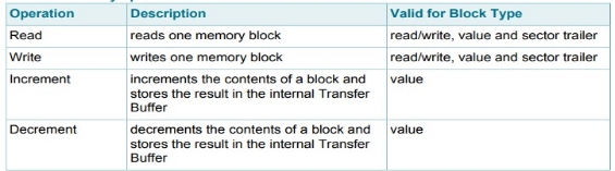
VALUE BLOCKS
Value blocks allow performing electronic purse functions (valid commands are: read, write, increment, decrement, restore, transfer).Value blocks have a fixed data format which permits error detection and correction and a backup management. A value block can only be generated through a write operation in value block format:
• Value: Signifies a signed 4-byte value. The lowest significant byte of a value is stored in the lowest address byte. Negative values are stored in standard 2´s complement format. For reasons of data integrity and security, a value is stored three times, twice non-inverted and once inverted.
• Adr: Signifies a 1-byte address, which can be used to save the storage address of a block, when implementing a powerful backup management. The address byte is stored four times, twice inverted and non-inverted. During increment, decrement, restore and transfer operations the address remains unchanged. It can only be altered via a write command.
SECTOR TRAILER
The sector trailer is the last block (block 3) in one sector. Each sector has a sector trailer containing the
• secret keys A (mandatory) and B (optional), which return logical “0"s when read and
• the access conditions for the blocks of that sector, which are stored in bytes 6…9. The access bits also specify the type (data or value) of the data blocks. If key B is not needed, the last 6 bytes of the sector trailer can be used as data bytes.
The access bits for the sector trailer have to be configured accordingly
All keys are set to FFFF FFFF FFFFh at chip delivery and the bytes 6, 7 and 8 are set to FF0780h.
Default value of smart cards at delivery FF 07 80
MEMORY ACCESS
Before any memory operation can be done, the card has to be selected and authenticated. Before any memory operation can be done, the card has to be selected and authenticated.
ACCESS CONDITIONS
The access conditions for every data block and sector trailer are defined by 3 bits, which are stored non-inverted and inverted in the sector trailer of the specified sector. The access bits control the rights of memory access using the secret keys A and B. The access conditions may be altered, provided one knows the relevant key and the current access condition allows this operation. Remark: With each memory access the internal logic verifies the format of the access conditions. If it detects a format violation the whole sector is irreversibly blocked. Remark: In the following description the access bits are mentioned in the non-inverted mode only. The internal logic of the MF1S50yyX/V1 ensures that the commands are executed only after a successful authentication.
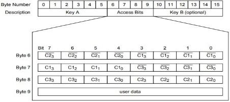
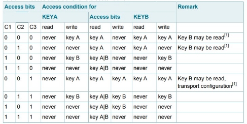
ACCESS CONDITIONS FOR THE SECTOR TRAILER
Depending on the access bits for the sector trailer (block 3) the read/write access to the keys and the access bits is specified as ‘never’, ‘key A’, ‘key B’ or key A|B’ (key A or key B). On chip delivery the access conditions for the sector trailers and key A are predefined as transport configuration. Since key B may be read in the transport configuration, new cards must be authenticated with key A. Since the access bits themselves can also be blocked, special care has to be taken during the personalization of cards.
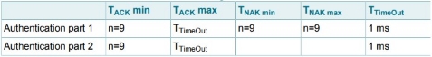
1.1 MIFARE CLASSIC AUTHENTICATION
The MIFARE Classic authentication is a 3-pass mutual authentication which needs two pairs of command-response. These two parts, MIFARE Classic authentication part 1 and part 2 are shown below
Part-1
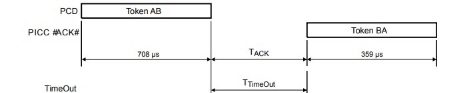
Part-2
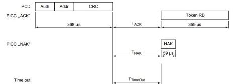
MIFARE Classic Read Timing
1.2 MIFARE READ
The MIFARE Read requires a block address, and returns the 16 bytes of one MIFARE Classic block.
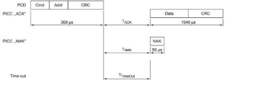
MIFARE Read Timing

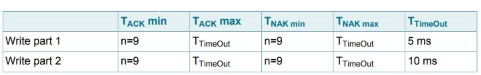
MIFARE WRITE
The MIFARE Write requires a block address, and writes 16 bytes of data into the addressed MIFARE Classic EV1 with 1K memory block. It needs two pairs of command-response. These two parts, MIFARE Write part 1 and part 2 are shown below
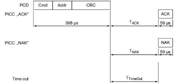
Part-1
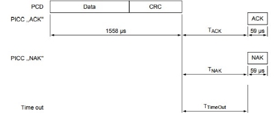
Part-2
MIFARE WRITE TIMING
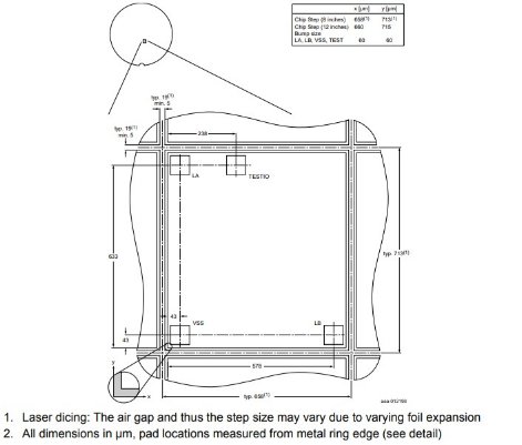
BARE DIE OUTLINE
Coin/Token
Coin/Token are determined by the first 2 values i.e. “32”. Card/Token have almost the same working as smart cards except that it can just be read and not write which makes it almost impossible to hack/bypass unless any other method is applied.
Conclusion
It is possible to hack/bypass smart cards as they can be easily cloned by a cloner and therefore has a severe flaw. Some cities have adapted to new technologies to protect their user base like using NFC/HF technology whereas the only metro city which uses LF technology is Kolkata.
So my final verdict is that all technologies are vulnerable and if we do deep research, we can point out some flaw in that. This is just a try from our side and we will keep researching on it.
Authors – Pritam Das, Nirjhar Barma and Kanouj Bose.